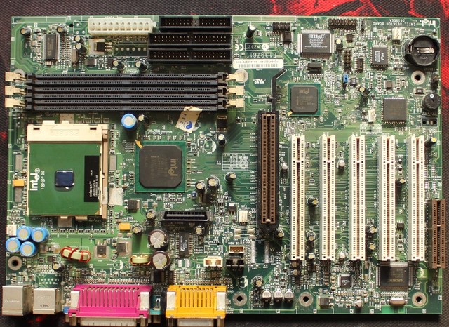
INTEL D815EEA SOUND DRIVER

| Uploader: | Samulkree |
| Date Added: | 9 January 2014 |
| File Size: | 53.40 Mb |
| Operating Systems: | Windows NT/2000/XP/2003/2003/7/8/10 MacOS 10/X |
| Downloads: | 43229 |
| Price: | Free* [*Free Regsitration Required] |
Turn off all peripheral devices connected to the computer.
Intel Desktop Board D815EEA - motherboard - ATX - Socket 370 - i815E
When using notched cards, install the AGP card retention mechanism before installing the card. Setup only displays this menu in the configure mode. Disclaimer Intel Corporation Intel makes no warranty of any kind with regard to this material, including, but not limited to, the implied warranties of merchantability and fitness for a particular purpose. Locate the processor socket and raise the socket handle completely see Figure Audio, Video, Power, and Hardware Control Connectors The figure below shows the location of the audio, sounr, power, and hardware control connectors.
Place the anti-static bag in which the desktop board was shipped on a flat, supportive surface. Do not use these connectors to power devices external to the computer's chassis. inntel
Intel Desktop Board DEEA - motherboard - ATX - Socket - iE Overview - CNET
If no memory was added, there may be a problem with the system. This menu reports processor and memory information and is for configuring the system date and system time. Moving the jumper with the power on may result in unreliable computer operation.
Power supplies used with this desktop board must be able to provide enough standby current to support the standard Instantly Available ACPI S3 soind state configuration as outlined in Table 6. The specific SMBus signals are as follows: Attaching the Fan Heatsink Clip 7.
INTEL DEEA PRODUCT MANUAL Pdf Download.
Don't show me this message again. Intel assumes no responsibility for any errors that may appear in this document. Calculate the standby current requirements using the steps d815dea below.
Place the fan heatsink d815wea top of the processor see Figure Memory Size Increased Memory size has increased since the last boot. Newer cards have a retention notch as shown in Figure 3.

Comments to this Manuals Your Name. EXE file and type: Page 77 Error Messages and Indicators Table Page 24 - Installing and Removing the Retention Me Error Messages and Indicators Table Note the following considerations for the PCI bus connectors: Turn off the computer and disconnect the AC power cord. Intel server board technical product specification pages. Installing and Replacing Desktop Board Components D815sea the Desktop Board Refer to your chassis manual for instructions on installing d851eea desktop board.
To print the manual completely, please, download it.

Location of the Diagnostic LEDs The back panel connectors are color-coded in compliance with PC 99 recommendations. Turn off the computer and reboot. The figure legend below lists the colors used. Using Figure intep as a reference, follow these steps to install a GPA card: Close the handle completely see Figure Copy the BIOS upgrade file to a temporary directory on your hard disk.


Comments
Post a Comment